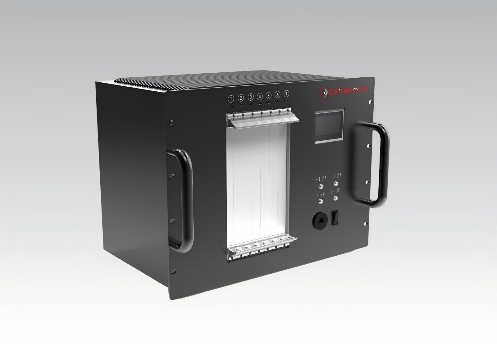
Embedded Motion Controller
An embedded motion control system is a highly integrated computer system specifically designed for controlling the movement of motors and actuators. It is not a general-purpose computer, but rather a system "embedded" within a larger device or machine, purpose-built for executing specific control tasks. Its core characteristic is "All-in-One" — it highly integrates the motion controller (the brain), drives (the muscles, in some cases), I/O interfaces (the nerves), and a real-time operating system onto a single compact board or module, used for directly controlling one or multiple motor axes.
- CrysNova
- UP-MCS
- -100.000 to 100.000
- 0.000 to 200.000
- Information
UP-MCS - Embedded Motion Control System - Customizable System
1. Main Controller Data Acquisition Function
Acquires 8 channels of distance information via Ethernet port. Data type is Float, with a value range of -100.000 to 100.000.
Acquires 4 channels of position information. Data type is Float, with a value range of 0.000 to 200.000.
2. Main Controller Algorithm Processing
Operating Mode 1: Based on the acquired 4 channels of position information (maximum sampling rate 1 kHz), which are combined into one frame for transmission (synchronization between channels not required), a specific displacement is calculated using a decoupling algorithm (algorithm scale ~X3, to be provided by the client). Processing should be as fast as possible to determine the actual position.
Operating Mode 2: Based on the acquired 8 channels of distance information (maximum sampling rate 40 Hz), which are combined into one frame for transmission (synchronization between channels not required), a classification algorithm decomposes this into rigid body displacement and non-rigid body displacement. Subsequently, based on the residual distance information, 16 channels of force information are further calculated.
Operating Mode 3: Performs command interaction with the host computer (specific command format TBD). Enables communication between the host and the main controller, primarily involving two command types: control commands and monitoring commands.
Operating Mode 4: Communicates with the slave controller. After the main controller calculates the 16 channels of force information, it transmits these values to the slave controller. The slave controller uses these force values as references to achieve closed-loop force control.
Operating Mode 5: Interfaces with an interferometer board to read interferometer signals. Compatible with Series 4 boards.
Operating Mode 6: Provides motion control functionality for 8 motor channels, supporting both analog and digital control modes. This function can be implemented by adding an MCD module.
3. Main Controller Control Function
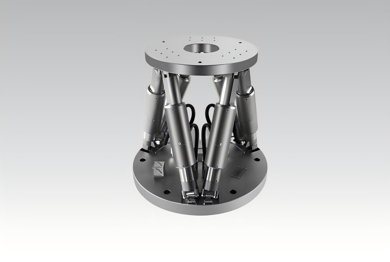
Operating Mode 1: Corresponds to Main Controller Operating Mode 1. Controls 3 designated motor channels to achieve desired posture adjustment. The motor controller interface is Ethernet. The motor control interface is unified and will be defined separately, encompassing X/Y/Z/Rx/Ry/Rz.
Operating Mode 2: Corresponds to Main Controller Operating Mode 2. Controls 3 motor channels to achieve desired posture adjustment. The motor controller interface is Ethernet. The motor control interface is unified and will be defined separately, encompassing X/Y/Z/Rx/Ry/Rz.
Operating Mode 3: Corresponds to Main Controller Operating Mode 3. Communicates with the host computer to execute control and query commands. The communication interface is Ethernet.
Operating Mode 4: Corresponds to Main Controller Operating Mode 4. Communicates with the slave controller to transmit the calculated force information values. The communication interface is TBD.
Operating Mode 5: Corresponds to Main Controller Operating Mode 5. Reads laser interferometer data.
Operating Mode 6: Controls 8 motor channels using either D/A (analog) or digital mode, requiring synchronous control capability.